
This is part 1 of the blog series "Measuring pressure difference in practice", in which we use hands-on tests to find out what really affects the results of pressure difference measurements – and what doesn't.
Part 1: The effect of equipment (this article) – How do the material, length and type of tube affect the results?
Part 2: The effect of placement – How does the positioning and installation of the meter affect the results?
Part 3: The effect of wind – How do wind direction and strength affect a building's pressure difference?
Why did we test this?
Pressure difference measurement is one of the basic tools of indoor air investigations in buildings – but setting it up always involves a bit of DIY: drilling holes, connecting tubes and so on. That means plenty of choices to make, and just as many chances to get it wrong. In this blog we wanted to find out for ourselves how much the measuring equipment itself affects the results. There are all sorts of rules of thumb and bits of "common knowledge" about what kind of tube you should or shouldn't use, how long it can be, and whether you can use a capillary tube instead of tubing and drilled holes.
We decided to stop guessing and test it ourselves.
More about the meters
Pressure difference meters can broadly be divided into two categories:
-
"Diaphragm meters" suited to spot measurements
-
"Flow-based meters" suited to continuous measurement
Here we discuss and test meters designed for continuous measurement, along with their accessories. There are several manufacturers, but all these meters work on broadly the same principles, so the results of these tests should apply to most of them.
The Guide to measuring pressure differences in buildings (2019, in Finnish), prepared by A-Insinöörit for the Finnish Ministry of the Environment, is an excellent and comprehensive guide to carrying out pressure difference measurements. We recommend it to anyone who carries out or commissions them. In this blog we put a few claims made in the guide and elsewhere in the industry to a practical test. And yes, we've made some of these claims ourselves. :)
TL;DR
-
With 3-metre tubes, length already affects the result, but not significantly. The material (PVC/silicone) has no effect on the results.
-
A 10-metre PVC tube dampens the results significantly – by about 20%
-
Without a compensation algorithm, a capillary tube does not work at all in continuous flow-based measurement
-
Loopshore's capillary tube compensation algorithm corrects the error, but it still isn't perfect
-
Soft silicone tubing does not react to external pressure fluctuations.
The claims under test
Before we reach for the roll of tape and the reel of tubing, let's list what we're actually testing:
- "Keep tubes as short as possible" – but what counts as short? – Loopshore user manual
- A capillary tube cannot be used in continuous, flow-based measurement – Loopshore installation guide
- The capillary tube compensation algorithm corrects the error caused by the capillary tube – Loopshore installation guide
- "Soft-walled tubing should not be used in long measurement lines, because pressure fluctuations in other spaces may affect the measurement result" – A-Insinöörit measurement guide, p. 30
Test setup
Test site
Our test laboratory was an 80-year-old two-storey detached house with natural ventilation. The exhaust air from the shower room and the kitchen cooker hood is connected to the same flue, which has a roof fan at the top. On the test day the outdoor temperature was about +6 °C and a moderate, gusty wind was blowing, which may show up as fluctuation in the results.
Equipment
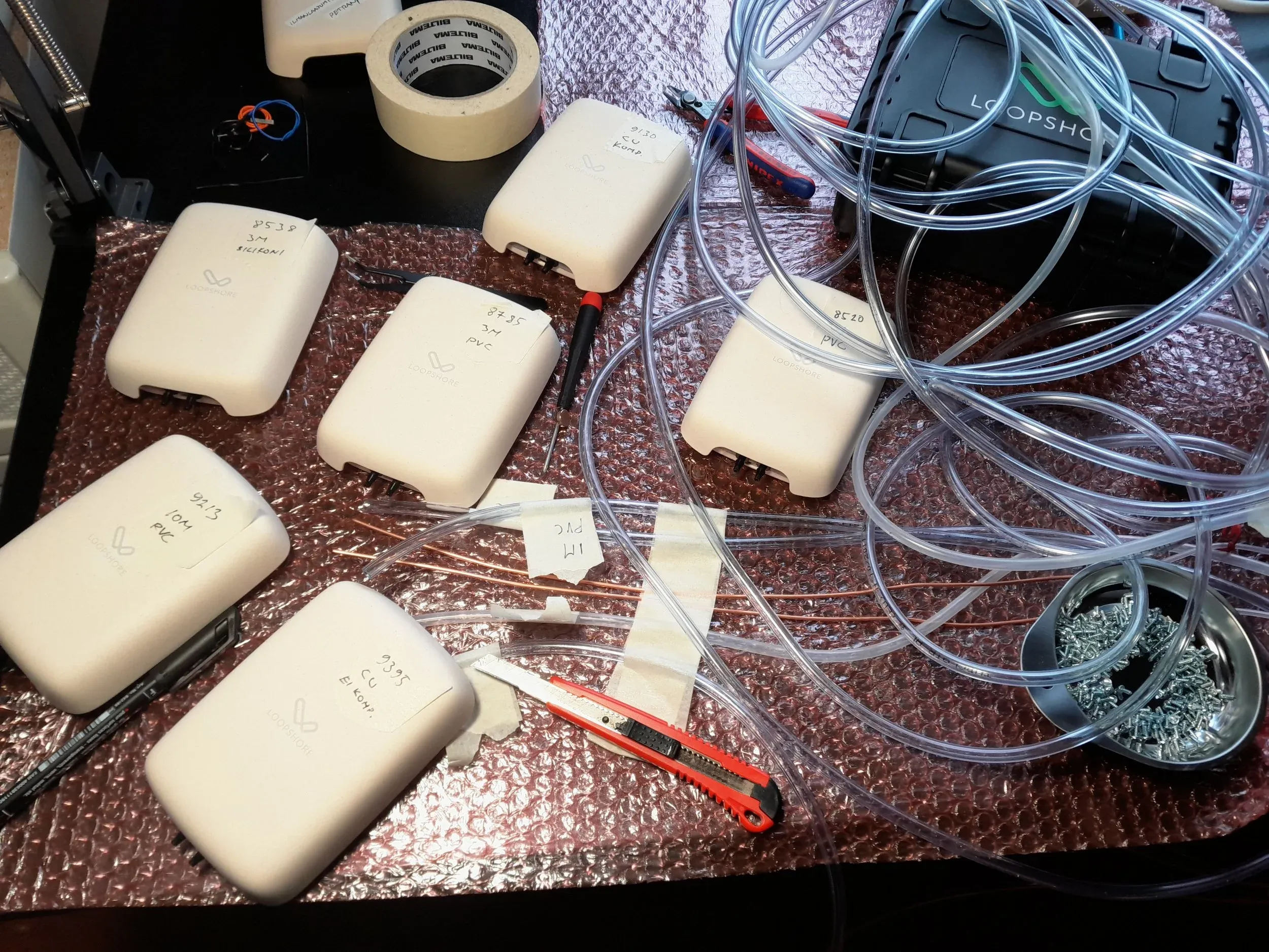
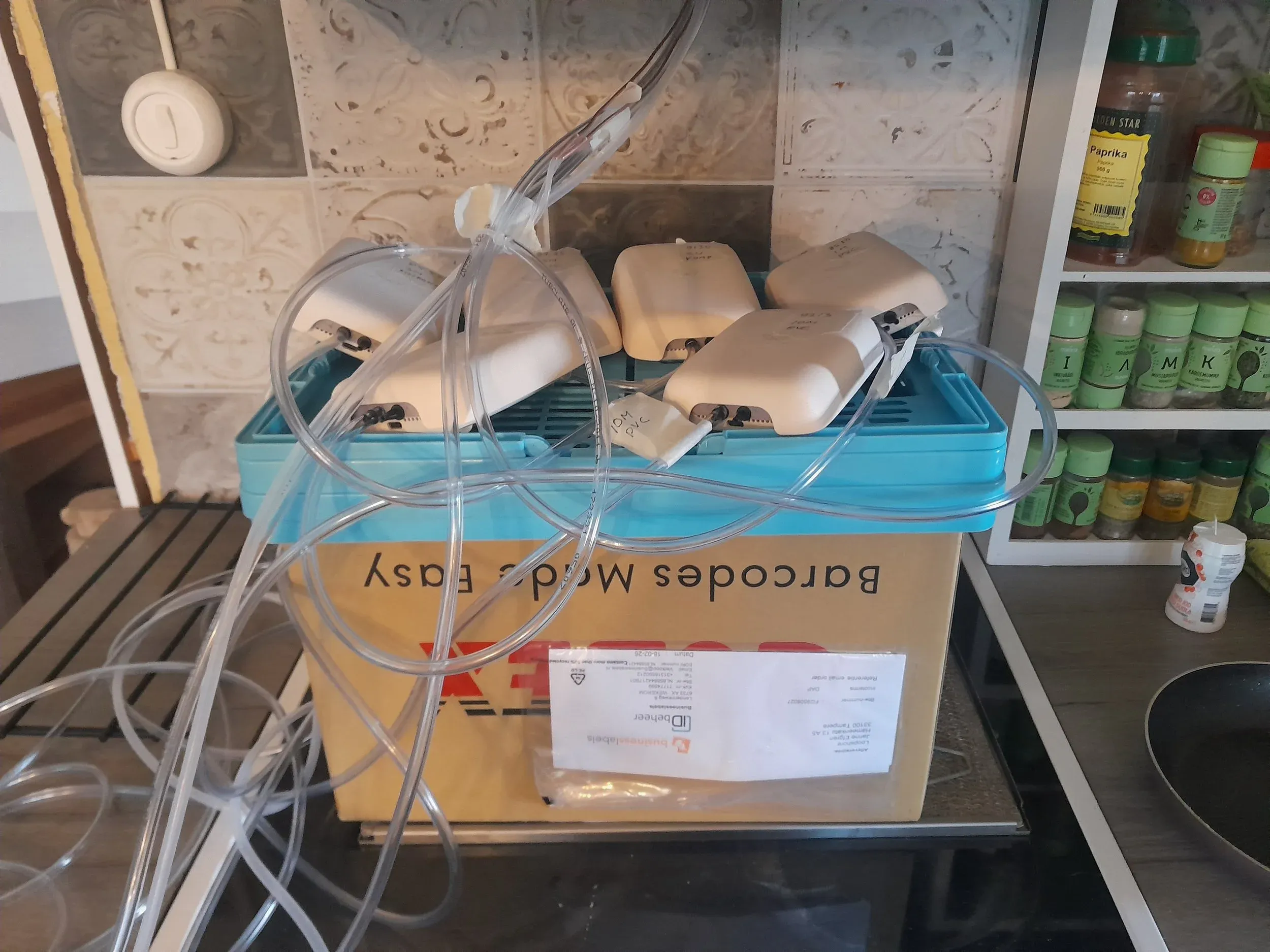
Six Loop Delta pressure difference meters were used in the test, each connected to a different measuring tube:
- 9130 Copper tube (capillary) ~40 cm + ~60 cm PVC, compensation algorithm on
- 9395 Copper tube (capillary) ~40 cm + ~60 cm PVC, no compensation
- 8520 PVC tube 1 m
- 8785 PVC tube 3 m
- 9213 PVC tube 10 m
- 8538 Silicone tube 3 m
All devices were set to Normal measurement mode and the reporting interval was shortened to one minute. On one device (9130), the capillary tube compensation algorithm was switched on.
A shower room as a pressure chamber
For the test we needed a space whose pressure difference we could adjust in a controlled way. We chose the shower room, whose exhaust air is connected to the roof fan via the chimney. Creating negative pressure was simple:
- We taped over most of the supply air openings
- We adjusted the negative pressure using the roof fan's power settings
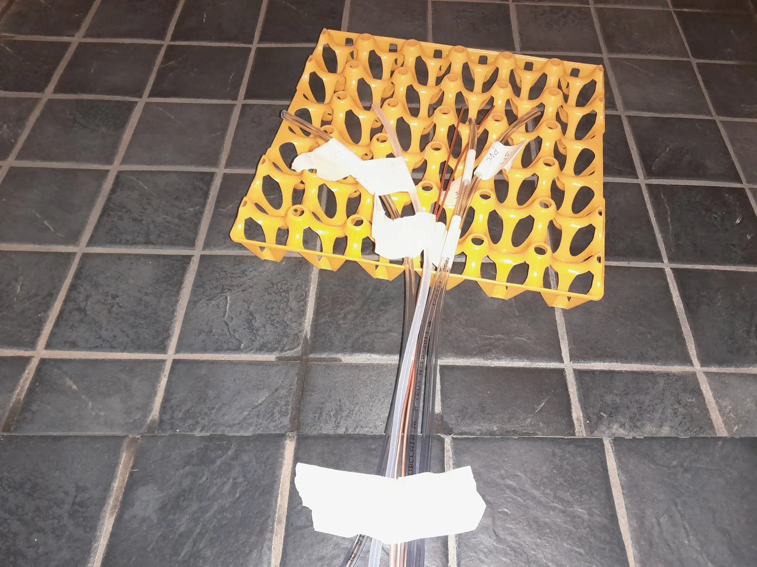
The devices were placed outside the shower room, in the utility room, and only the ends of the measuring tubes were led under the door into the shower room.
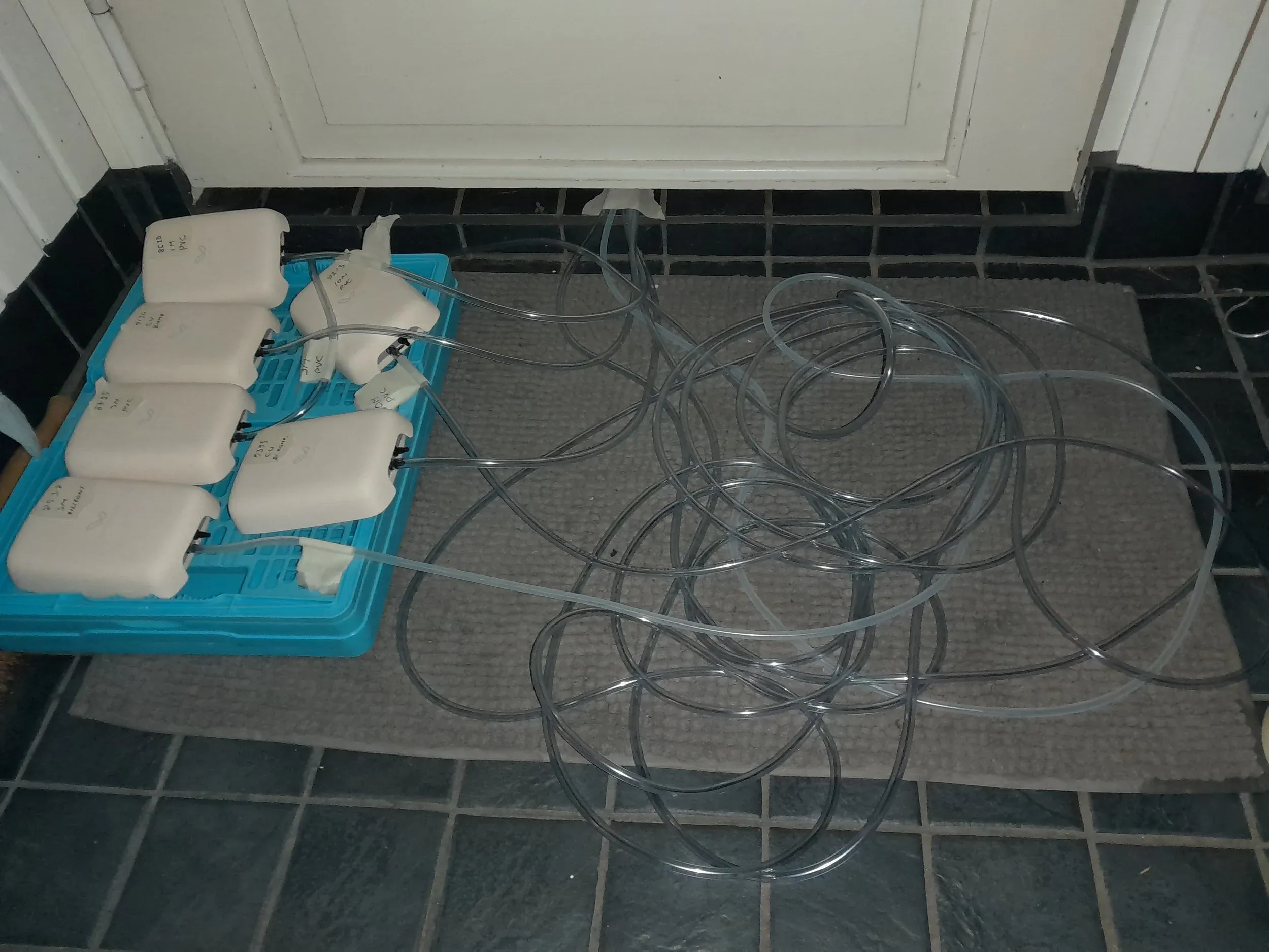
Connection: why the plus port?
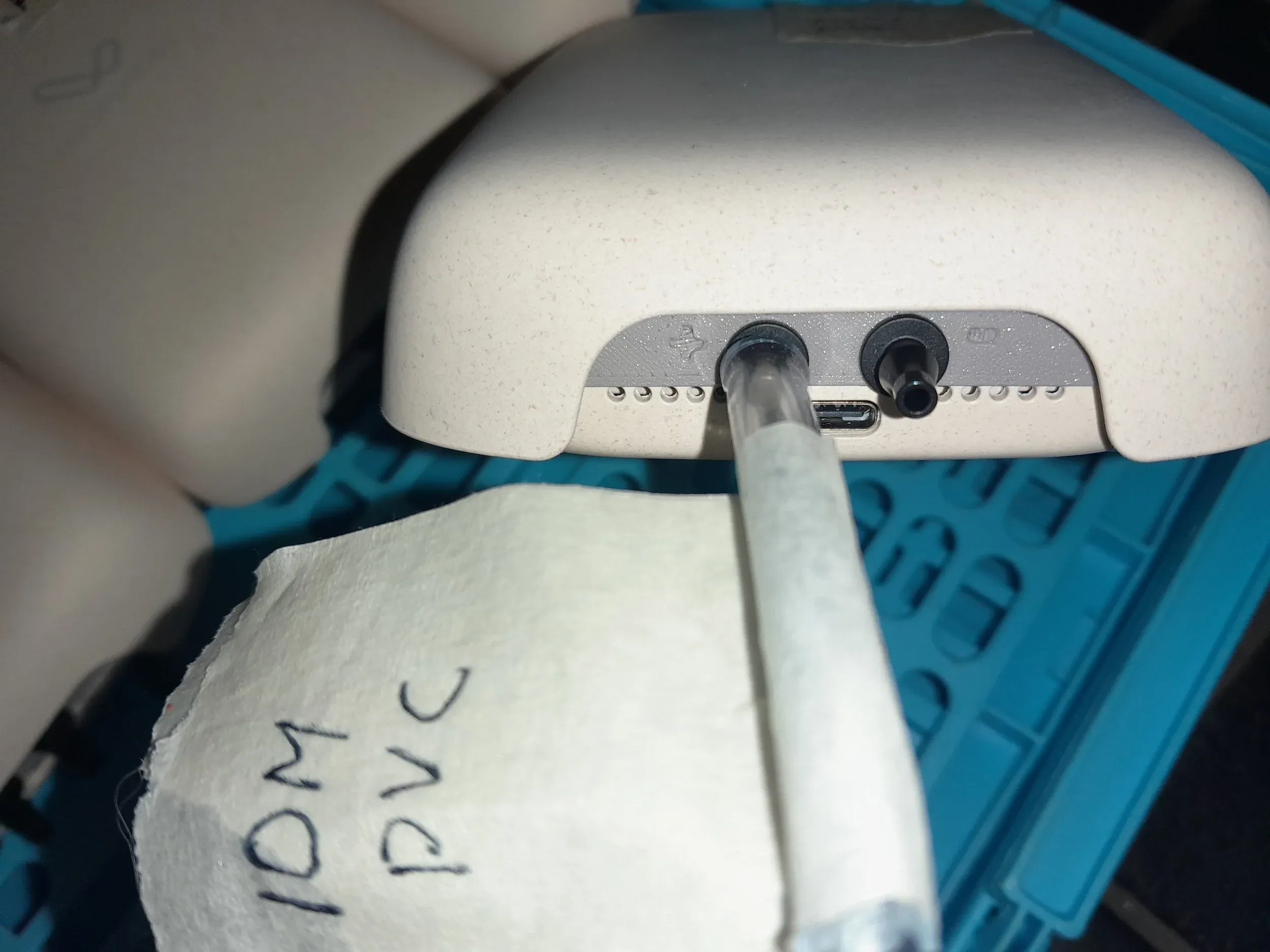
In a normal pressure difference measurement, the device is indoors and a tube runs outdoors from the device's minus port (−). Negative pressure indoors then shows up as a negative reading.
In this test, however, the situation is reversed: the devices are outside the shower room and the tubes run into the shower room, which is under negative pressure. That's why we connected the tubes to the plus port (+), so that the negative pressure in the shower room still shows up as a negative reading in the service.
Test 1: Zero levels – variation between devices
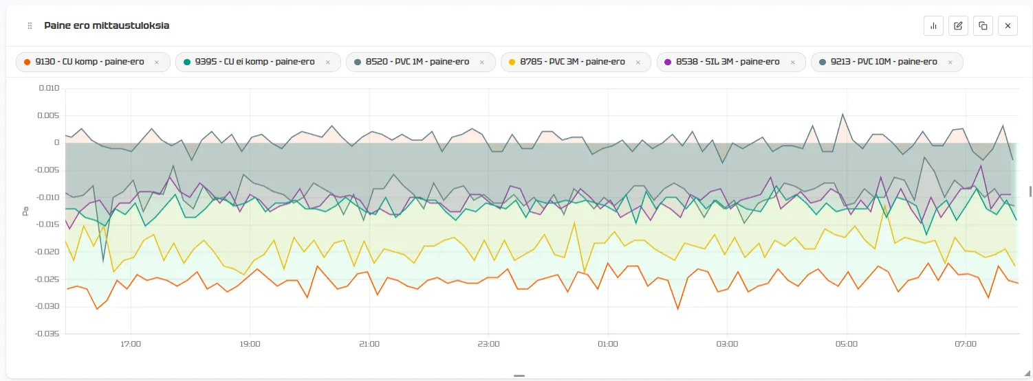
Before we measure anything at all, let's check the baseline. The night before, all six devices were left measuring in open air without tubes. Both ports are then exposed to the same pressure, so the result should be exactly 0.00 Pa.
The devices' zero levels settle between −0.03 and +0.005 Pa. Loop Delta's stated zero-point accuracy is ±0.08 Pa, so all the devices are comfortably within limits.
Test 2: Shower room – small pressure differences
Stage 1: Fan off and at low power
Tubes connected, fan off. What do we see?
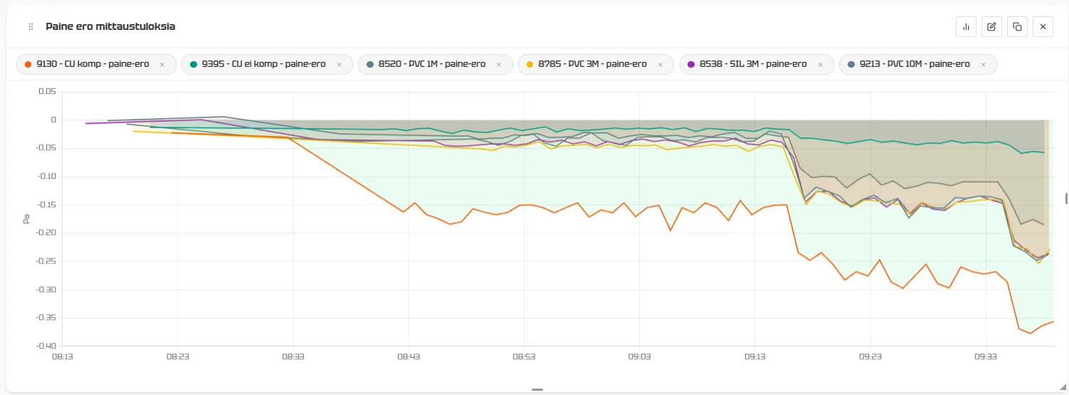
Even before the fan is switched on, there is a slight negative pressure in the shower room. This is perfectly normal: the exhaust duct acts as a chimney, and the temperature difference between outdoor and indoor air creates a natural draught – the stack effect.
As soon as the tubes are connected, we make our first interesting observation: both capillary tube measurements (compensated and uncompensated) differ slightly from the others right from the start. The difference is less than 0.1 Pa, however, which is within the device's stated accuracy. The scale of the chart makes the difference look more dramatic than it is. The 10 m PVC tube also differs from the three tubes in the same bundle.
Stage 2: Turning up the power – differences start to appear
As the roof fan's power is increased step by step, the devices start telling different stories:
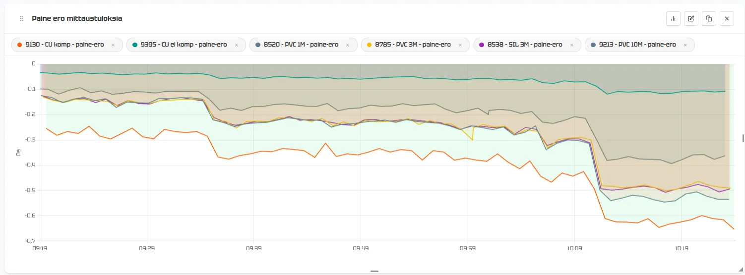
With the fan at full power, the negative pressure in the shower room reaches only about −0.5 Pa. This shows how much make-up air the shower room gets from under the door and through other gaps – the fan can't create significant negative pressure, because air gets in faster than it can be extracted.
Time to bring out the heavy artillery.
Stage 3: Taping the door and further sealing
Next, we taped shut:
- The kitchen cooker hood, whose damper doesn't close completely (and we cleaned the grease filter while we were at it – testing involves housework too)
- The shower room door, all the way round
Now the pressure difference really started to show:
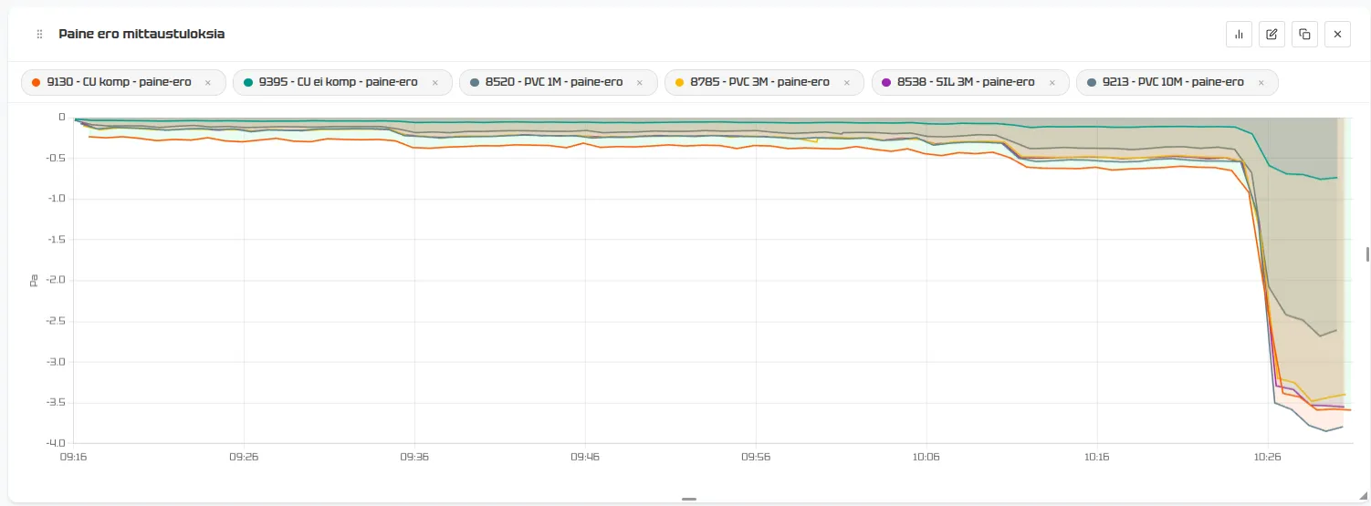
After taping, the maximum negative pressure was about −3.5 Pa – already closer to the pressure differences created by mechanical exhaust ventilation. At this level, the differences between the equipment become clearly visible:
Clear observations:
- Uncompensated capillary tube (9395): Gets stuck close to zero. The measurement simply doesn't work. The capillary tube's 0.8 mm inner diameter resists airflow so much that the pressure doesn't have time to equalise between measurements.
- Compensated capillary tube (9130): At very low pressures, it measures higher values than the others. At −3.5 Pa it shows practically the same as the 3 m tubes.
- 10 m PVC tube (9213): Lags clearly behind the others. It shows about −2.5 Pa when the others show −3.5 Pa.
- 1 m PVC vs 3 m PVC and 3 m silicone: The 3 m tubes show about 0.2–0.5 Pa less than the 1 m tube, which we treat as the correct result here.
Test 3: Ventilation duct – large pressure differences
With small pressure differences, the differences are small. But what happens when the pressure difference is tens of pascals?
We moved the devices to a different spot and led the tube ends directly into the exhaust air duct. Now we're measuring the negative pressure created by the fan in the duct directly. This should produce negative pressures that don't really occur in buildings in practice.
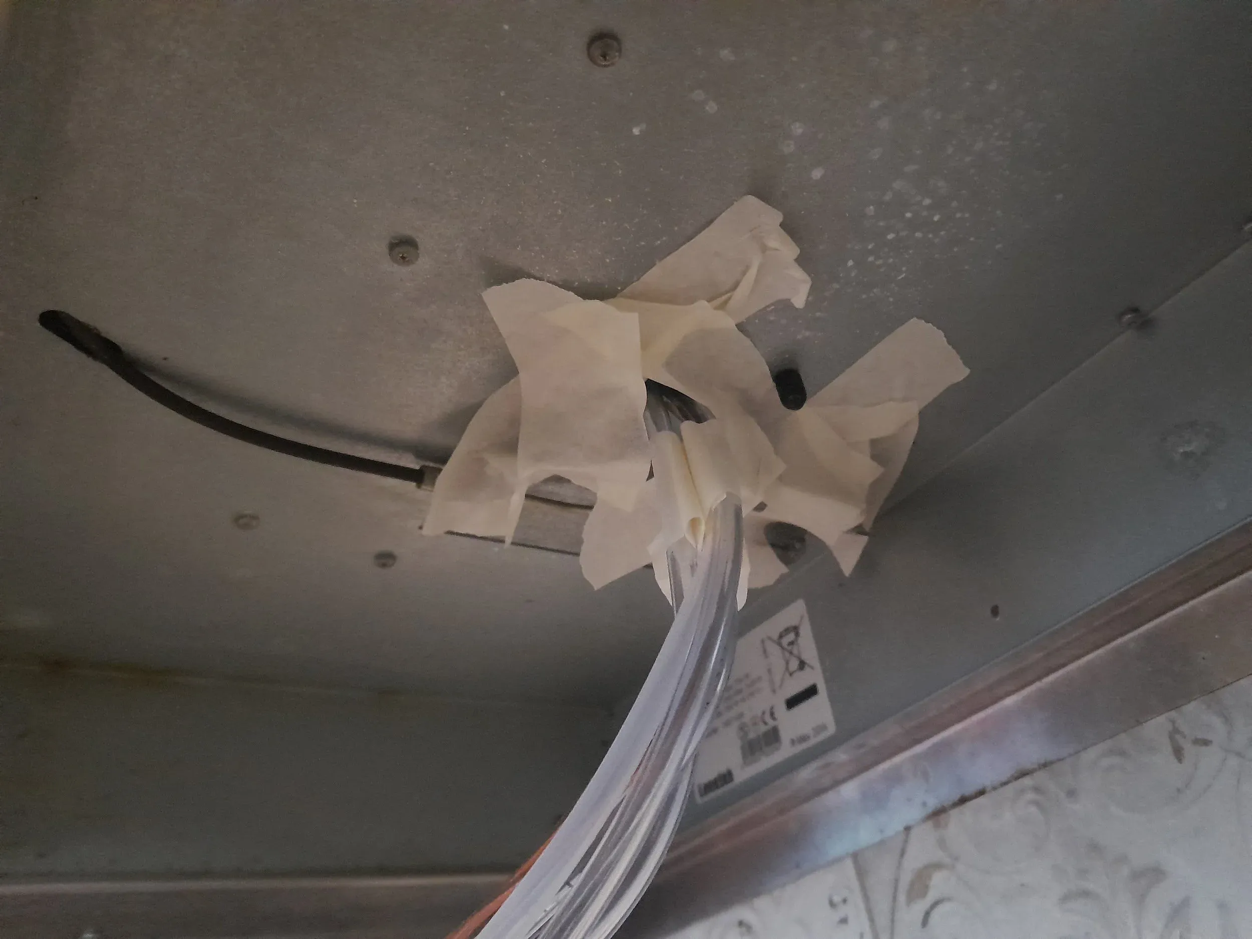
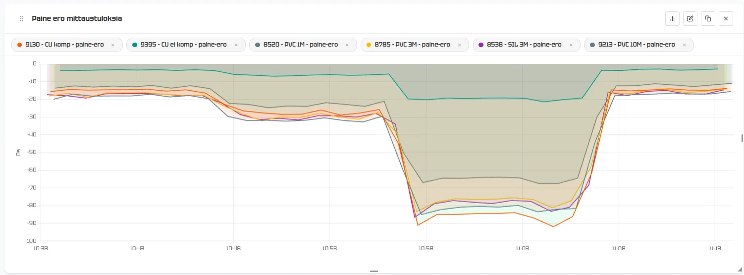
The results confirm the same observations as at lower pressures, only even more clearly:
- Copper, no compensation ~20 Pa Doesn't work
- 10 m PVC ~65 Pa 20% error
- Copper, compensated ~85 Pa ~5% (overcorrection)
- The 3 m tubes show a few Pa less than the 1 m tube
Test 4: Does external pressure affect silicone tubing?
The A-Insinöörit measurement guide (p. 30) states:
"Soft-walled tubing, such as silicone tubing, should not be used in long measurement lines, because pressure fluctuations in other spaces may then affect the measurement result."
We were sceptical about this claim. Our theory was that pressure fluctuations might change the tube's diameter by a few parts per thousand, which is hardly enough to affect the measurement. So we decided to test it.
Test arrangement
With the ventilation duct conveniently open, we seized the opportunity:
- We took a 3 m silicone tube and wound about 2 m of it into a coil
- We pushed the coil inside the ventilation duct – so the tube was bathed in the airflow running through the duct
- Both ends of the tube come out of the duct: one connected to the device, the other in open air next to it
- Since both ends are at the same pressure (outside the duct), the pressure difference should be exactly 0 Pa
- If external pressure affected the tube, it would show up as a deviation from zero
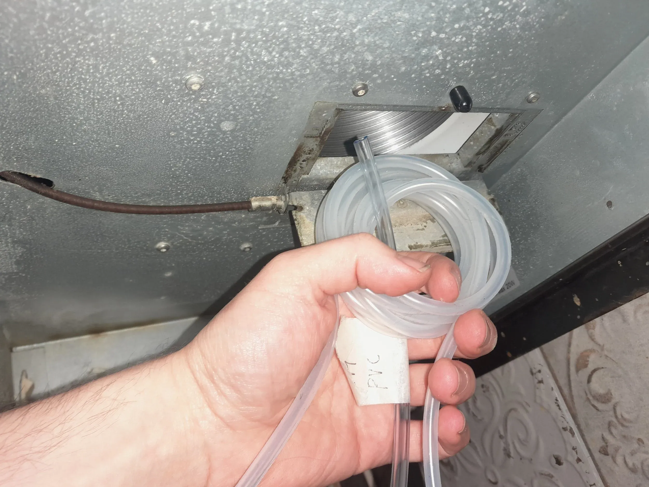
At the same time, another device measured the pressure difference in the duct itself, so that we could be sure the silicone tube really was exposed to varying pressure.
We tested in two ways:
- Static pressure: Fan at different power settings, waiting for the pressure to stabilise
- Dynamic pressure: Fan alternating between full power and off at intervals of about 15 seconds – the pressure in the duct varies by an estimated 0–80 Pa
Since Loop Delta takes several readings during each one-minute reporting period and also reports the minimum and maximum values, momentary pressure fluctuations should show up in the min/max values, even if they are smoothed out of the average, which aims to reflect the effective pressure difference in the duct during that minute.
Results
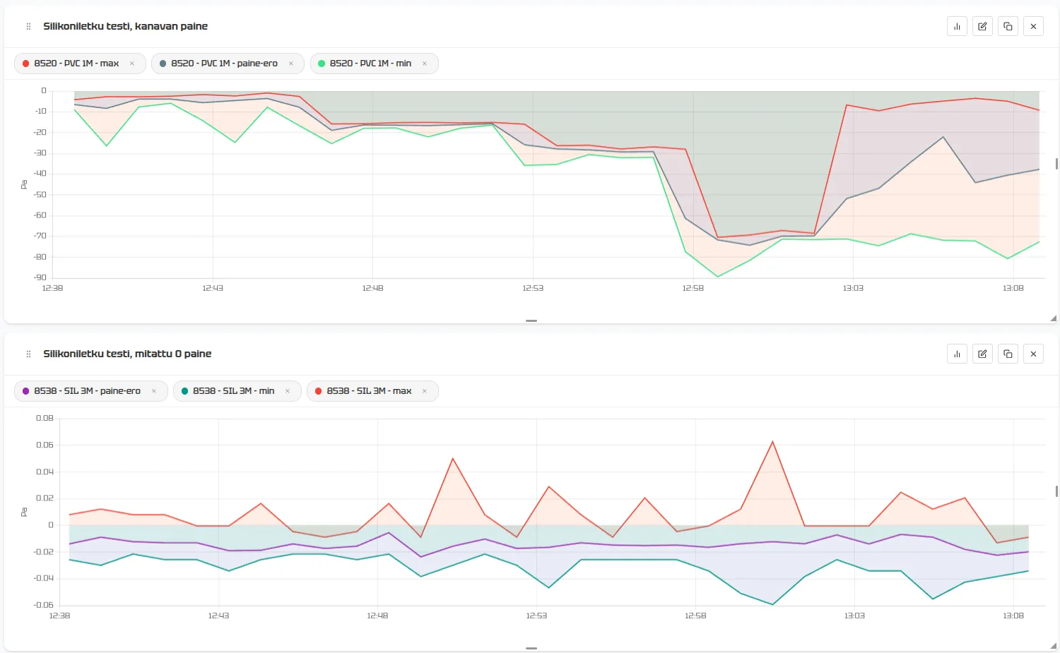
There's nothing quite like realising you were wrong – but this time, perhaps we weren't.
The chart shows quite clearly: even though the pressure outside the tube varies between 0 and 80 Pa, both statically and dynamically, it does not show up in the silicone tube's readings in any meaningful way. There may be slight variation in the min/max peaks, but the amplitude is in the order of 0.05 Pa – completely insignificant.
So why does the measurement guide warn about it?
The guide was written in 2019, and it isn't necessarily wrong in the general case. Possible reasons for the warning:
- Very thin-walled or poor-quality silicone tubing might behave differently
- On very long lines (tens of metres), the effect could add up
- The warning may also have a practical origin: silicone tubing attracts dust through static electricity and gets squashed very easily. It's a poor choice in any case.
In our test – with standard 4/7 mm silicone tubing over a length of 2–3 metres – the claim was not borne out.
Summary
1. "Keep tubes as short as possible" → confirmed
Based on the tests, you could say that short means 2 metres. 3 metres is still acceptable, but the measurement error already amounts to a few per cent. With a 10 m tube, you need to be prepared for an error of around 20%.
2. A capillary tube cannot be used in continuous, flow-based measurement → possible
A capillary tube can be used, but it requires compensation: without it, the measurement did not work at all in our test. Loopshore's Loop Delta meter has this compensation. If you use another meter, make sure its manufacturer offers equivalent compensation.
3. The capillary tube compensation algorithm corrects the error caused by the capillary tube → confirmed
The error caused by the tube can be corrected, and although this may still leave a measurement error of a few per cent, it can sometimes be the sensible option (e.g. in a listed building where you really shouldn't be drilling holes).
4. Soft-walled tubing should not be used in long measurement lines, because pressure fluctuations in other spaces may affect the measurement result → refuted
Pressure acting on the measuring tube from outside does not cause measurement error.
Practical recommendations
- Use a short tube. A PVC or silicone tube under 2 metres gives a reliable result. At 3 m the error is not yet significant. A longer tube must either have a larger inner diameter, or the result must be corrected by calculation.
- If you use a capillary tube, compensation is a must. Without it, the measurement doesn't work.
- Don't stress about the tube material. PVC and silicone give practically the same result – choose whichever is most convenient for the installation.
Notes on tubing – practical installation experience
The copper tube connector (the joint between the capillary tube and the tubing) kinks and gets squashed very easily, so you need to be careful when installing it. One careless bend and the measurement won't work.
PVC tubing may even be easier to handle than the much floppier silicone tubing. That said, pushing PVC tubing onto the connector, and especially pulling it off again, takes considerably more force.
Silicone tubing has two practical weaknesses:
-
It attracts every speck of dust and stray hair through static electricity
-
It is easily squashed under weight or in tight bends, and at worst "sticks" itself shut
In the next part, we look at how the placement of the meter and the tubes affects the results – in other words, whether it matters at what height the meter and the tube end are placed, and how the tubes are routed.